|
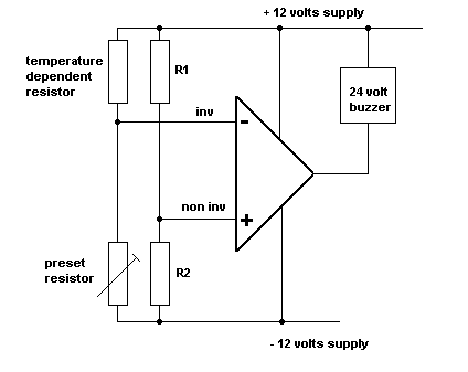 This circuit is configured as a comparator. R1 and R2 provide a fixed reference voltage at the non inverting input. The inverting input voltage is set by the other two resistors. If the voltage at the inverting input rises above the reference voltage, then the the output goes to minus 12 volts and the buzzer is
energized.
The behavior of the circuit can be changed by swapping the preset and temperature dependent resistors.
Light dependent resistors etc can replace the temperature dependent one. |