|
Materials
Circuit
Pin RB7 to 1Kohm resistor. Resistor to LED. LED to ground.
Pin RD1 to 10/47Kohm resistor. Resistor to ground.
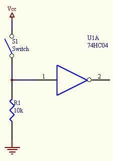
Pin RD1 to switch. Switch to power.
This circuit has a “pull-down resistor”. When the switch is closed, the PIC
reads 5 volts and when it is open it reads 0 volts. If we had no pull down
resistor then the pin would be in a “floating” state when the switch was open,
meaning that the voltage can fluctuate. We need to connect the pin to ground so
the PIC always reads 0 when the switch is open. If there was a wire connected to
ground instead of a resistor, it would create a short that burns up the circuit.
Code
#include <16F877A.h>
#device adc=8
#FUSES NOWDT //No Watch Dog Timer
#FUSES HS
//Highspeed Osc > 4mhz
#FUSES PUT
//Power Up Timer
#FUSES NOPROTECT //Code not protected from reading
#FUSES NODEBUG //No Debug mode for ICD
#FUSES NOBROWNOUT //No brownout reset
#FUSES NOLVP //No low voltage prgming,
B3(PIC16) or B5(PIC18) used for I/O
#FUSES NOCPD //No EE protection
#use delay(clock=20000000) // Sets crystal oscillator at 20 megahertz
#use rs232(baud=9600, xmit=PIN_C6, invert) // serial port output & baud rate
//close switch to see LED turn on
//open switch to see LED turn off
//if the pin is low (0 volts) x = 0, or FALSE
//if the pin is high (5 volts) x = 1, or TRUE
void main() {
int x = 0;
while(true){
x = input(PIN_D1);
if(x==1){
output_high(PIN_B7);
}
else{
output_low(PIN_B7);
}
}
} |