|
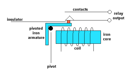
The electromagnetic
relay consists of a
multi-turn coil, wound
on an iron core, to form
an electromagnet.
When the coil is
energised, by passing
current through it, the
core becomes temporarily
magnetised.

The magnetised core
attracts the iron
armature.
The armature is pivoted
which causes it to
operate one or more sets
of contacts.
When the coil is de-energised
the armature and
contacts are released.
The coil can be
energised from a low
power source such as a
transistor while the
contacts can switch high
powers such as the mains
supply.
The relay can also be
situated remotely from
the control source.
Relays can generate a
very high voltage across
the coil when switched
off.
This can damage other
components in the
circuit.
To prevent this a diode
is connected across the
coil.
The cathode of the diode
is connected to the most
positive end of the
coil.
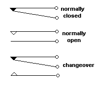
 The springsets
(contacts) can be a
mixture of n.o n.c and
c.o.Look at the page on
switches to see how they
can be used in circuits.
Various coil operating
voltages (ac and dc) are
available.
The actual contact
points on the springsets
are available for high
current and low current
operation.
The REED RELAY has a
much faster operation
than the relays
described above. |