|
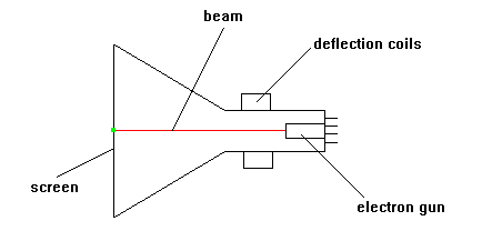
The Cathode Ray Tube
(CRT) is used in
oscilloscopes, radar,
monitors and television
receivers. It consists
of a glass envelope made
from a neck and cone.
All air has been
extracted so that it
contains a vacuum.
At the narrow end are
pins which make
connection with an
internal ELECTRON GUN.
Voltages are applied to
this gun to produce a
beam of electrons.
This electron beam is
projected towards the
inside face of the
screen.
The face is coated with
a PHOSPHOR which
PHOSPHORESCES (glows)
when hit by the beam.
This produces a spot of
light on the centre of
the face of the CRT.
By varying the beam
current, spot BRIGHTNESS
can be controlled.
Controlling the diameter
of the beam controls
FOCUS.
Phosphors come in a
range of colours.
On its way from the gun
to the screen the beam
passes between 2 sets
of plates.
They are called the X
and Y plates (as in
graphs).
By applying voltages to
these plates the beam
can be deflected.
This causes the spot to
move from the centre of
the screen to another
position on the screen.
The X plates plates
deflect the spot
horizontally, the Y
plates vertically.
Thus the spot can be
deflected to any
position on the screen.
External deflection
coils are often used
instead of the internal
deflection plates.
Note that dropping a CRT
causes it to IMPLODE
which is as dangerous as
an explosion. |