|
The 7 segment display is
used as a numerical
indicator on many types
of test equipment.
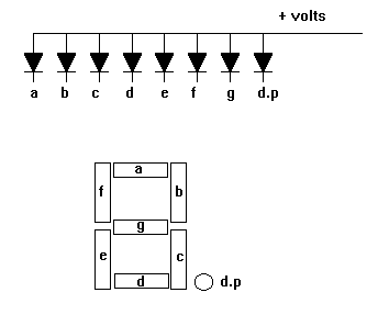
It is an assembly of
light emitting diodes
which can be powered
individually.
They most commonly emit
red light.
They are arranged and
labeled as shown in the
diagram.
Powering all the segments will display the number 8.
Powering a,b,c d and g
will display the number
3.
Numbers 0 to 9 can be
displayed.
The d.p represents a
decimal point.
The one shown is a
common anode display
since all anodes are
joined together and go
to the positive supply.
The cathodes are
connected individually
to zero volts.
Resistors must be placed
in series with each
diode to limit the
current through each
diode to a safe value.
Early wrist watches used
this type of display but
they used so much
current that the display
was normally switched
off. To see the time you
had to push a button.
Common cathode displays
where all the cathodes
are joined are also
available.
Liquid crystal displays
do a similar job and
consume much less power.
Alphanumeric displays
are available which can
show letters as well as
numbers. |