|
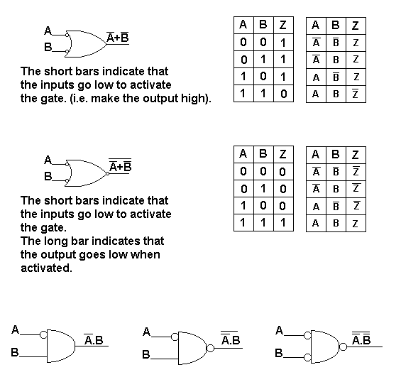
 A "bubble" on the output
of a NAND indicates that
the gate output goes low
when the inputs are
activated.
Bubbles on inputs mean
that these inputs go low
to activate the gate.
In the low activated AND
shown above, both inputs
must go low to make the
output go high.
In the low activated OR
below, A or B going low
makes the output go
high.
In the low activated NOR
circuit, A or B going
low makes the output go
low.
A long bar above the
output indicates that
the output goes low when
the gate is activated.
The short bars indicate
that those inputs must
go low to activate the
gate.
 |