|
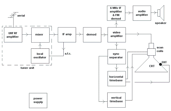
The tuner unit converts
the incoming sound and vision carriers to
their IF frequencies.
For more information on
how this is done, read
the page on AM radios.
The oscillator is
protected against
frequency drift, due to
temperature changes, by
the Automatic Frequency
Control (AFC).
The IF amplifier has a
bandwidth wide enough to
pass both sound (33.5
MHz) and vision (39.5
MHz) IF signals and
their sidebands.
The video signal is
demodulated and
amplified and is used to
control the brightness
at each particular point
on the screen.
The sync pulses are
separated from the
composite video signal
by the sync separator.
These pulses are used to
control the frequencies
of the time bases,
ensuring that they run
at the same speed as,
and in phase with, those
in the studio cameras.
The time bases provide
saw tooth waveforms
which scan the face of
the CRT, while the video
signal controls the
brightness at each point
on the screen.
See the page on mono
cameras to read about
scanning.
The line time base also
supplies the Extra High
Tension (EHT) voltage
for the CRT final anode.
This voltage is very
high and dangerous.
Due to a mixing process
between the sound and
vision carriers, the
sound signal appears as
a 6 MHz FM signal at the
video output stage.
It is amplified and
demodulated.
The resulting audio
signal is amplified and
used to drive a
loudspeaker.
A power supply supplies
DC voltages to all
stages. |