|

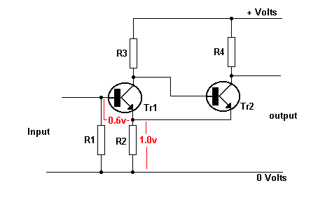
With no signal in,Tr1 has no forward bias and is cut off. The collector voltage of Tr1 is high, turning Tr2 on. The emitter current of Tr2 flowing through R2 produces 1 volt across R2.
Since the base of Tr1 is at zero volts, the base/emitter junction of Tr1 is reverse biased by 1 volt. The input signal has to exceed this voltage plus 0.6 volts (1+0.6 = 1.6 volts) to forward bias Tr1.
INPUT GOES HIGH TO MAKE OUTPUT HIGH
The input signal increases from zero. Once the input voltage exceeds 1.6 volts,Tr1 begins to conduct. Its collector voltage starts to fall and the base voltage of Tr2 falls. The emitter current of Tr2 through falls, reducing the voltage across it.
This further increases the conduction of Tr1, producing a cumulative effect.
Tr1 comes on very rapidly and Tr2 goes off. Tr2 collector voltage goes high.
INPUT GOES LOW TO MAKE OUTPUT LOW
When the input voltage falls, it has to go below 0.6 volts before Tr1 collector current starts to fall. Again there is a cumulative action which rapidly turns Tr1 off and Tr2 on. Tr2 collector voltage falls. The difference in the values of Tr1 base TURN ON and TURN OFF voltages is known as
HYSTERESIS.
The
Schmitt
Trigger
can be
used to
clean up
noisy
signals
or to
speed up
slow
rise and
fall
times of
pulses. |