|
By Alex Meaden
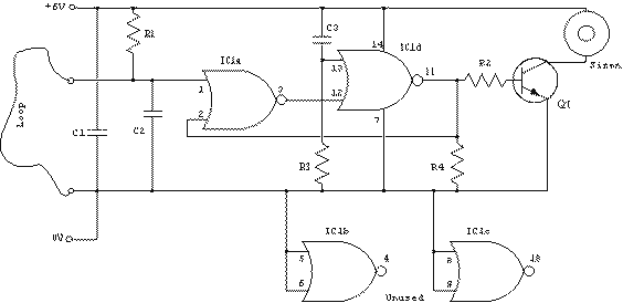
This circuit is a simple wire loop alarm that can be used in doorways, hallways, or any other place the tripwire will be broken by intruders. The circuit has a built in siren, but it can be replaced by a relay to drive an external siren, commercial alarm, etc.
Schematic
Parts:
| Part | Total Qty. | Description | Substitutions | | R1 | 1 | 100K 1/2W 1% Resistor | | | R2, R4 | 2 | 10K 1/2W 1% Resistor | | | R3 | 1 | 1 Meg 1/2W 1% Resistor | | | C1, C3 | 2 | 0.1uF Ceramic Disc Capacitor | | | C2 | 1 | 0.01uF Ceramic Disc Capacitor | | | IC1 | 1 | 4001UBE Quad 2-i/p NOR Gate | | | Q1 | 1 | MPSA14 Low Power NPN Transistor | | | SIREN | 1 | Micro piezo siren 12V DC 150mA, 110dB @ 1M | | | LOOP | 1 | See "Notes" | | | MISC | 1 | Board, Wire, Socket For IC1 | |
Notes:
- The loop can be any type of hookup wire, with a maximum resistance of about 90K. Using very thin wire (40AWG, for example) will make a very sensitive trip wire, but will shorten the distance it can be strung due to the high resistance.
- The siren can be replaced with a relay to drive external loads.
|