Engineering Projects
WiFi Analog and Digital Signal Sensor
with MQTT protocol
Author: Horacio Bouzas Email:
hbouzas@yahoo.com
The brain: ESP8266 MCU
I have been working on a water level sensor for the rain
barrels I have installed at home. The rain barrels feed
drip lines into a vegetable garden. I wanted to track
water levels through time, activate a pump at watering
times, fill the barrel if it gets too empty. I thought
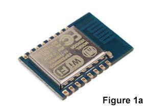
again of using the ESP8266 Wifi microcontroller, but
since I needed an Analog to digital converter I opted
for the ESP8266 ESP-12 version (figure 1a).
Lets look at the ESP8266 principles first to refresh
our minds.
The ESP8266 ESP-12 is a very small WIFI enabled
microcontroller. It can be programmed in C by flashing
it with the manufacturer’s (Espressif) software
development kit (SDK). But it can also be programmed in
LUA using the NodeMCU SDK (open source, just Google it
or go to GitHub). LUA is a scripting language used
widely in the gaming industry and I picked it to program
the ESP8266 because of being compact, very high level
and allowed rapid prototyping. The ESP8266 acts as an
access point and/or a WIFI station, so once it is
configured it acquires an IP address and then you can
communicate with it via a web browser or a TCP
connection (phone, tablet, computer, etc).
The ESP-12 has 9 GPIOs and an Analog Digital Converter
(ADC). For this project we will only use the ADC and one
GPIO.
There is plenty of material out there to get anyone
going with this little wonder. The key things to know is
that you will need a USB to serial module to initially
talk to the ESP8266, be familiar
with serial communication and able to do some script
programming. For USB to serial, any FTDI232 based module
will pretty much work, but be careful as they are
counterfeit FTDI232 that can render useless, make sure
whatever you get is genuine. Then you need to choose a
serial terminal to send commands to the serial module
that will send commands to the ESP8266. Something like
CoolTerm or SSCOM32 would do the job. I use CoolTerm
mostly on the Mac. Also, when you start copying LUA code
into the module, CoolTerm does a great job. With this
brief introduction to the ESP8266, you can have a lot of
fun prototyping all kinds of interesting WIFI projects.

Figure 2a shows the pins and connections on the
ESP8266 ESP-12:
VCC: 3.3 Volts
CH_PD: Module enable, connect to VCC
RST: Resets the module when pulled to GND
UTXD: Serial transmit
URXD: Serial receive
GPIO: General purpose IO
ADC: Analog Digital Converter
GND: Ground
Principles of operation
The analog/digital sensor module reads analog data and
digital data through its 2 input terminals.
Input analog data limits are zero VDC to 3.3VDC, and
this maps into output values of 0 to 1024.
Input digital data limits are zero, for a digital zero,
and 3.3VDC for a digital 1.
The module sends the value of the measured analog data
periodically every Interval milliseconds,
and it sends the value of the measured digital data when
this changes from 0 to 1 or from 1 to 0. The user can
also request the module to send the measured values of
analog and/or digital data at any time by publishing a
specific MQTT topic; more on this later.
The module provides a triggering signal whenever the
digital data changes (Figure 1).
The module provides a triggering signal when the analog
signal is less than a preset value or larger than a
preset value (Figure 2).


Setting up the module using a web browser:
- Connect the 5V power
- Press board reset button
- From your computer, check available wireless networks
and connect to a network which name
has the form ESP_STATION_xxxxxxx
- When prompted, enter the password to the ESP_STATION.
The preset password is ‘espadmin’
- Wait until your computer successfully connects to
ESP_STATION_xxxxxxx
- From your web browser and after station is connected
enter the following address and WIFI
network SSID and password:
192.168.4.1/?SSID=Your_SSID&Password=Your_password&Server=Your_Server&Port=Your_Por
t&Interval=Interval_in_milliseconds&MinAnlg=min_analog_trigger&MaxAnlg=max_analog_trigge
r
Where:
SSID= your WIFI router SSID
Password= your WIFI router
password
Server=the IP address of the
MQTT server to connect to
Port= the MQTT server port
(def=1883)
Interval= the interval (in
integer milliseconds) to send analog data to the MQTT
server
(def=5000 ms)
MinAnlg= when the analog
signal is less than min_analog_trigger, LED 1 turns on
and terminal pin 1 turns on (def=300)
MaxAnlg= when the analog
signal is greater than max_analog_trigger, LED 2 turns
on and
terminal pin 2 turns on (def=800)
Interval= the interval (in
integer seconds) to send analog data to the server
- Reset the board
Operating and communicating with the module
Once the module is connected to the WiFi router it
will establish communication with the MQTT
server and port as specified above and will attempt to
connect. Wait a few seconds and all 4 LEDs
will blink in sequence indicating a successful
connection. If this fails, reset the board and wait a
few seconds for the LED sequence. The module uses MQTT
protocol for communication. MQTT topics are composed of
a four letter acronym followed by the ESP822 chipid (the
chipid is listed with your documentation), XXXXchipid
Once a connection with the MQTT sever is established,
the module is ready for communication and
therefore reading analog and digital data and sending
commands.
A typical MQTT instruction is composed of a topic
followed by a message.
MQTT Topics and Messages
RANLchipid : this topic instructs the
module to read a sample of the analog data and send it
back via an MQTT topic and message. The module in
response sends a topic and value as follows:
DANLchipid value ; you can get the analog value
by subscribing to the topic DANLchipid and getting the
value from the message
RDIGchipid : this topic instructs the
module to read a sample of the digital data and send it
back via an MQTT topic with the value as a message. The
module in response sends a topic and value as
follows:
RANLchipid value ; you can get the digital
value by subscribing to the topic RANLchipid and getting
the value from the message
MANLchipid min_analog_trigger (min 0, max
1024, def 300): this topic allows the user to set the
module’s minimum analog value used for triggering the
LED and signal . The change takes immediate effect.
XANLchipid max_analog_trigger (min 0, max
1024, def 800):: this topic allows the user to set the
module’s maximum analog value used for triggering the
LED and signal. The change takes immediate effect.
INTEchipid Interval_in_milliseconds (min
500 ms, max 240000 ms, def 5000 ms): this topic allows
the user to set a new interval in milliseconds for
receiving analog data. The change takes immediate
effect.
RESTchipid: this topic allows the user to
reset the module remotely.
The source code
interval= 5000
minanl= 300
maxanl= 800
--dig_pin = 6 -- GPIO12
if file.open("servport.txt","r") ~= nil then
server=file.readline()
port=file.readline()
interval = tonumber(file.readline())
minanl =tonumber(file.readline())
maxanl =tonumber(file.readline())
file.close()
else
wifi.sta.config("","XXXXXXXX")
node.restart()
end
gpio.mode(6,gpio.INPUT)
gpio.mode(6,gpio.INT)
gpio.mode(2,gpio.OUTPUT)
gpio.mode(1,gpio.OUTPUT)
gpio.mode(7,gpio.OUTPUT)
gpio.mode(5,gpio.OUTPUT)
gpio.write(2,gpio.LOW)
gpio.write(1,gpio.LOW)
gpio.write(7,gpio.LOW)
gpio.write(5,gpio.LOW)
mqttStatus = false
chipid = tostring(node.chipid())
m = mqtt.Client( "ESP8266-" .. chipid, 0, "user", "pwd")
function mqttConnect()
m:connect(server, port, 0, function(conn)
print("Connected to MQTT:" .. server .. ":" .. port .."
as " .. "ESP8266-" .. chipid )
mqtt_sub()
mqttStatus = true
gpio.write(2,gpio.LOW)
tmr.delay(500000)
gpio.write(2,gpio.HIGH)
gpio.write(1,gpio.LOW)
tmr.delay(500000)
gpio.write(1,gpio.HIGH)
gpio.write(7,gpio.LOW)
tmr.delay(500000)
gpio.write(7,gpio.HIGH)
gpio.write(5,gpio.LOW)
tmr.delay(500000)
gpio.write(5,gpio.HIGH)
tmr.delay(2000000)
gpio.write(2,gpio.LOW)
gpio.write(1,gpio.LOW)
gpio.write(7,gpio.LOW)
gpio.write(5,gpio.LOW)
end)
end
print "Connecting to MQTT broker 1. Please wait..."
mqttConnect()
function mqtt_sub()
m:subscribe("RANL" .. node.chipid() , 0, function(conn)
end)
m:subscribe("RDIG" .. node.chipid() , 0, function(conn)
end)
m:subscribe("MANL" .. node.chipid() , 0, function(conn)
end)
m:subscribe("XANL" .. node.chipid() , 0, function(conn)
end)
m:subscribe("INTE" .. node.chipid() , 0, function(conn)
end)
run_main_prog()
end
function publish_data(topic, payload)
if string.sub(topic, 1, 4) == "RANL" then
onAnalog()
elseif string.sub(topic, 1, 4) == "RDIG" then
onDigital()
elseif string.sub(topic, 1, 4) == "MANL" then
minanl=tonumber(payload)
print(minanl)
elseif string.sub(topic, 1, 4) == "XANL" then
maxanl=tonumber(payload)
print(maxanl)
elseif string.sub(topic, 1, 4) == "INTE" then
interval=tonumber(payload)
tmr.stop(4)
tmr.alarm( 4 , interval , 1 , onAnalog )
end
end
function onAnalog()
adcval=adc.read(0)
m:publish( "DANL" .. chipid, adcval ,0 ,0 ,
function(conn)
end)
if adcval and adcval < minanl then
gpio.write(7,gpio.LOW)
gpio.write(5,gpio.HIGH)
elseif adcval and adcval > maxanl then
gpio.write(5,gpio.LOW)
gpio.write(7,gpio.HIGH)
else
gpio.write(7,gpio.LOW)
gpio.write(5,gpio.LOW)
end
end
function onDigital()
digval=gpio.read(6)
m:publish( "DDIG" .. chipid, digval ,0 ,0 ,
function(conn)
end)
if digval and digval == 0 then
gpio.write(2,gpio.LOW)
gpio.write(1,gpio.HIGH)
elseif digval and digval == 1 then
gpio.write(1,gpio.LOW)
gpio.write(2,gpio.HIGH)
else
gpio.write(1,gpio.LOW)
gpio.write(2,gpio.LOW)
end
end
function run_main_prog()
gpio.trig(6, 'both', onDigital)
tmr.alarm( 4 , interval , 1 , onAnalog )
m:on("message", function(conn, topic, payload)
publish_data(topic, payload)
topic=nil
payload=nil
end )
m:on("offline",
function(con)
mqttStatus = false
print("Going offline" )
pub_sem = 0
current_topic = 1
topicsub_delay = 50
tmr.alarm(6, 1000, 1, function()
if mqttStatus then
tmr.stop(6)
else
mqttConnect()
end
end)
end)
end