Engineering Projects
4x1 WiFi Wireless Antenna Switch
Author: Horacio Bouzas
Email: hbouzas@yahoo.com
I started playing with electronics back when I was 10
years old in Argentina, where I grew up. Then I got my
ham radio operator license when I was 16 years old and I
was very active in the ham club and on the air. It was
then when I built my first vacuum tube transmitter and
refurbished and old receiver (also vacuum tubes) that
somebody from the club was throwing away. My interest
for science and electronics grew and I ended studying
physics but always tinkered with electronics, whenever I
could.
I’ve moved a lot around the world for work (oil and gas) so my dedication to ham radio pretty much faded away. But it came back! Just recently, I got my ham radio operator license back and started to get active on 2mtr and on digital.
Due to lack of space outdoors, I had to settle for installing my center fed dipole on the attic (I have a long attic), but I quickly realized I needed more than 1 antenna. 80 mtr, 40 mtr, 20mtr…. And I didn’t want to run multiple lines to the attic, so an antenna switch was necessary.
I bought a 4 position manual antenna switch and very
quickly realized (again) that I did not want to go up
and down the stairs with kids and wife sleeping to
switch the antenna. And more importantly, I did not want
to run another set of cables to drive a wired remote
controlled one. Wireless was the solution. I checked the
prices, and they were outside of my budget for a switch.
So, what’s next? I came up with an idea. Get a
RaspberryPi and add a relay board and then I have my
WIFI wireless relay control. Add some UHF female SO-239s
and we have a WIFI Antenna Switch. Well, two problems
with this, first it is really clunky connecting all
those coaxial cables to the relays and there would be a
lot of signal loss (and good luck tuning that), its
bulky and pretty difficult to assemble in one unit and
that would not work properly; second, it was more
expensive than I expected, even DIY it was around 100
dollars. I built it anyway and, well it worked for a
while. But I was not happy so I looked around and came
up with a better idea (or so I thought!). I found the
ESP8266, a WIFI module which is small, cheap, I mean
3-dollars-cheap and fully programmable. Combining this
module with a standard relay switch design, I thought I
had a solution for way under 100.00 dollars integrated
all in one single PCB board, suitable for mounting on a
proper box. Lets look at the design.
The brain of the switch
The ESP8266 is a very small WIFI enabled
microcontroller. It can be programmed in C by flashing
it with the manufacturer’s (Espressif) software
development kit (SDK). But it can also be programmed in
LUA using the NodeMCU SDK (open source, just Google it
or go to GitHub). LUA is a scripting language used
widely in the gaming industry and I picked it to program
the ESP8266 because of being compact, very high level
and allowed rapid prototyping.
The ESP8266 acts as an access point and/or a WIFI
station, so once it is configured it acquires an IP
address and then you can communicate with it via a web
browser or a TCP connection
(phone, tablet, computer, etc).
The ESP8266-01 used in this project, has 2 GPIOs, GPIO0 and GPIO2, meaning that we can program the module so it can read and write stuff on these GPIOs. The ‘stuff’ is simply digital signals, a 0 or a 1, or in volts, a few millivolts or 3.3 volts. This is perfect to drive LEDs or relays and make them open or close according to some logic and control either running on the module or instructed via a web or TCP server.
The module features a serial interface so you can
communicate with it to program it.
There is plenty of material out there to get anyone
going with this little wonder. The key things to know is
that you will need a USB to serial module to initially
talk to the ESP8266, be familiar with serial
communication and able to do some script programming.
For USB to serial, any FTDI232 based module will pretty
much work, but be careful as they are counterfeit
FTDI232 that can render useless, make sure whatever you
get is genuine. Then you need to choose a serial
terminal to send commands to the serial module that will
send commands to the ESP8266. Something like
CoolTerm or SSCOM32 would do the
job. I use CoolTerm mostly on the Mac. Also, when you
start copying LUA code into the module, CoolTerm does a
great job. With this brief introduction to the ESP8266,
you can have a lot of fun prototyping all kinds of
interesting WIFI projects.

Esp8266-01
Driving the relays
I looked a several relay types, and for this first version of the switch, I estimated going with something on the lower power side would be a wise choice, something that could handle 100-300 Watts. There is Esp8266-01 plenty of time to improve the design and make it robust for high power transmitters. I started with a 4 position switch, so I needed to drive 4 low power, low current relays. The ESP8266 has 2 GPIOs (general purpose IO), GPIO0 and GPIO2, but just 2 GPIOs, were not going to be able to drive 4 relays, I needed some logic. I decided to go with the 74HC238, a 3-to-8 line decoder. I just needed a 2-to-4 line decoder but since I had a bunch of these, lets use them, and connect the unused input line to ground. The ESP8266 GPIOs were going to feed the 74HC238 and provide the logic to switch the outputs, then these outputs will drive a Darlington power driver like the ULN2803. To make it safer, I decided to split the 8 ULN2803 outputs into 2 groups of 4, one group feeding the relays, the other the LEDs.
| GPIO0 | GPIO2 | Relay 1 | Relay 2 | Relay 3 | Relay 4 |
| 0 | 0 | H | L | L | L |
| 1 | 0 | L | H | L | L |
| 0 | 1 | L | L | H | L |
| 1 | 1 | L | L | L | H |
Figure 1
Figure 1 shows the desired truth table for the GPIOs and the Relays.
Now to achieve this logic, I connected GPIO0 to input A0 of the 74HC238 and GPIO2 to input A1. As mentioned above, A2 is connected to ground. This arrangement provides me with the correct output logic from the 74HC238 which I can now connect to the ULN2803. The cool thing here is that at all times, only one output is active, which is what we want when switching antennas. We don’t want 2 antennas connected to the transceiver at the same time! Or do we?
To make convenient I added a reset push button switch
and a flash switch, in case I needed to reset the board
for whatever reason, or flash it if I had new firmware.
The ESP8266-01 requires 3.3 V, and no more. The rest
of the board need 5V, so I needed an LM1117 3.3V
regulator to bring the voltage down and keep it stable.
4 LEDs indicate which antenna is active and 4 relays do
the switching as instructed by the ESP8266 and the logic
circuitry. The input and output connectors are standard
panel mount UHF female SO-239.
For safety, I included varistors at the feed point of
the relays.
Putting it all together
I programmed the ESP8266 so it can be configured via a web browser to connect to the WIFI router. Once configured, the module acquires an IP address and then I can communicate via TCP protocol. The module responds to the simple commands 1, 2, 3, 4 to switch between the antennas. TCP commands can be sent from a laptop or computer using a simple utility written in Python, for example. If using a mobile device, there are apps that send and receive TCP commands. But better yet, I went ahead and wrote an iPhone app that specifically pairs nicely with the antenna switch. Figure 2 shows a screen dump of the app (which should be available for free on the Apple app store under AntennaSwitch).
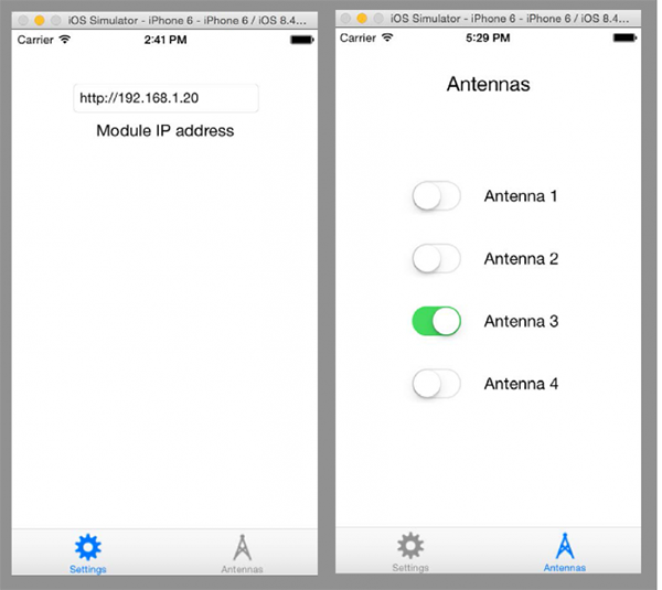
Figure 2
The final product
Figures 3a and 3b show the final PCB board and components. The finished board can be easily mounted in a metal box for safety and convenience. It only requires a 5 VDC small supply (250 ma). Figure 4 shows the schematic of the switch.
Figure 3a and 3b

Figure 4
Final thoughts and future enhancements
I was impressed of the performance and flexibility that the ESP8266 brings. Its small and extremely powerful and if you are interested in the Internet of Things (IoT), this module will allow you to hit the ground running. Being so small and modular it allowed me to integrate the UHF connectors, the relays, the logic circuits and the WIFI module all in one board that is 3 ¼ by 5 inches and can be easily mounted on any box.
Next steps are
- Increase the power handling to 1kW or more. The PCB board will have to be upgraded to handle this and I will need to find the right relays.
- Build a 6x1 or even 8x1 switch. Although 2 of the 4x1 can be easily combined, I think a compact 8x1 would be really nice.
- Foot massage (just kidding).
Finished kits of the Antenna Switch are available, email me for details at hbouzas@yahoo.com.