|

The same voltage is across the three components, since they are in parallel.
This is shown by the horizontal phasor.
Since the current through the resistor is in phase with the applied voltage, then it is shown on the same phasor.
Remembering CIVIL, capacitive current leads the voltage by 90 degrees, inductive current lags the voltage by 90 degrees.
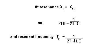
At resonance, the capacitor and inductor currents are equal and 180 degrees out of phase.
They therefore cancel each other out, and we are left with the effect of resistance only.
Since resistor voltage and current are in phase, the circuit voltage and current will be in phase.

A parallel resonant circuit has a high impedance. This is called the dynamic resistance. The formula is L/C*R. |